
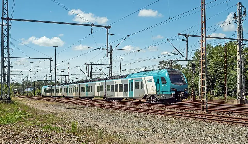
A catenary system contains a set of wires in mechanical contact with another wire or feeder. It mainly transports electricity from a substation to an electric train. The overall design of a catenary system depends on both the mechanical and electrical aspects of the railways.
In countries where the temperatures can alter between extremes, the catenary is one of the reaction components that undergo stress. This impacts its mechanical and electrical properties, creating problems that might bring the whole transport mechanism to a halt.
Contents
Working of a catenary
In its simplest form, a catenary supplies power to trains together with rails. A railway substation obtains a stepped-down voltage of medium ranges from their input 1500V DC systems. Another transformer further brings down this medium voltage.
A rectifier converts this low voltage to a direct current (DC). The catenary further connects to the positive DC supply while the rectifier’s negative terminal is connected to the rails. Thus, the catenary and rails form a circuit to complete the low-voltage DC power supply that the traction system needs.
Some of the aspects behind the design of a catenary system include:
- Train capacity
- The geographical location of the traction system
- Track profile
- Estimated Traffic
Possible issues with catenary
Trains and the whole traction system stay in constant exposure to outside weather. As a result, the catenary system always feels the impact of temperature, humidity, fog, and snow.
1. Delay in train schedules
The catenary cables might sag, or become taut, and in the worst cases, can collapse entirely. Such breakdown conditions in the catenary system can bring trains to an abrupt halt, causing inconvenience to passengers. Train schedule delays and cancellations can also occur due to the breakdown of the catenary system.
2. Contributes to traction energy losses
Not all the electrical power supplied to a traction system is utilized fully. A considerable amount of the energy provided is lost on its way, owing to its passage through multiple components and paths.
Most losses in the electrical traction system are dependent on the load. However, losses due to the catenary system contribute to a significant portion of these losses. As much as 70-85% of electric traction losses occur due to the cables of the catenary system because of their small cross-section.
This energy loss is released in the form of heat, thereby causing overheating in the catenary system. Notably, the overhead catenary wire losses are higher when compared to the return conductor and the rails. This is because the overhead catenary possesses a smaller cross-section and offers more resistance to the current flow and increases the heating losses.
The losses in catenary are attributed to Joule’s effect. The Ohmic Law P= I2R, where I is the current flowing in the cable and R, is the cable’s resistance to the current flow and explains it better.
Techniques to avoid overheating in the Catenary system
Electrical techniques
- Studies suggest that increasing the catenary cross-section at the feeder side might prevent overheating and related energy losses. This approach may lead to a more robust traction power supply, which means more power available to trains. Thus, trains can pick up acceleration and, in turn, helps meet train schedules too.
- Another suitable alternative would be to increase the contact wires’ cross-section, rather than at the feeders. This method also results in an enhancement in the various attributes of the contact wire, including:
- Reduction in the thermal stress due to the increase in the cross-section
- Increased lifetime
- Reduced failure rates
- Fewer maintenance costs
Alternative Methods to reduce the heating of catenary through electrical design include:
- Suitable arrangements to reduce the catenary system’s effective resistance in the loop starting from the substation to the train can help decrease the path’s resistance and thus the associated heating.
- An insulated feeder cable parallel to the track might serve as an option too. However, this might demand additional initial and running costs.
- For multiple track systems, cross-coupling the catenary at preset intervals helps in energy saving.
- Adopting another wire voltage range, preferably 25kV and 50 Hz, is theoretically another option, especially in European countries.
Mechanical techniques
Ensuring auto-tensioning in the cables can prevent the impact of ambient temperature on cables. By adding tension using additional weights or hydraulic tensioners, auto-tensioning can be plausible in cables.
As an additional measure, an extra midpoint anchor at the middle of the tension length helps limit the secondary wire movement in contact with the catenary. Tension length is proportional to the operating voltage. For instance, a 25kV line possesses a maximum tension length of 1970 meters.
Slashing the speed limits also prove helpful in lessening the cable collapses. For instance, a drop of traction speed from 90mph to 60mph was established to achieve similar results.
Frequently asked questions
How does a catenary system work?
A catenary system is a cable or chain that hangs in the shape of a parabolic curve, known as a catenary curve. The curve is determined by the weight of the cable and the tension applied to the ends. The cable will naturally hang in this shape due to the forces of gravity and tension. In practical applications, such as suspension bridges or power transmission lines, a catenary system is used to distribute weight and tension evenly along the length of the cable, providing stability and support.
What are the different types of catenary system?
There are a few different types of catenary systems, depending on the specific application. Some common types include:
- Simple catenary: This is the most basic type of catenary system, where a cable or chain hangs in a parabolic shape between two fixed points. This type of system is often used in suspension bridges or other structures where a cable is suspended between two points.
- Taut catenary: A taut catenary is similar to a simple catenary, but the cable is under tension, which causes the curve to be more flattened. This type of system is often used in power transmission lines, where the tension helps to keep the cable from sagging.
- Cable-stayed bridge: A cable-stayed bridge is a type of bridge that uses cables to support the roadway. The cables are anchored to the bridge’s towers and hang in a catenary shape to support the roadway.
- Cable-net structure: A cable-net structure is a type of tensile structure that uses a network of cables to support a membrane or fabric. The cables are anchored at the edges and form a catenary shape when loaded, creating a stable and efficient structure.
- Tensegrity structures: Tensegrity structures are structures composed of a combination of tension and compression elements, such as cables, rods, and struts. The cables are placed in a catenary shape and are tensioned to keep the structure stable.
Each type of catenary system is designed to suit specific needs and situations, depending on the weight and tension of the cable, the stability and support required, and the overall aesthetic and architectural design of the structure.
What is a catenary wiring system?
A catenary wiring system is a type of overhead electrical power distribution system that uses a series of wires suspended between poles or towers to transmit electricity. The wires are arranged in a catenary shape, which helps to distribute the weight of the wires and the tension evenly along the length of the system. The catenary shape is determined by the weight of the wires and the tension applied to the ends.
In a catenary wiring system, a conductor (usually made of aluminum or copper) is suspended between poles or towers by insulators. The conductor is typically suspended in a curve, which is called a catenary curve, that is determined by the weight of the conductor and the tension applied to the ends. The catenary shape helps to distribute the weight and tension evenly along the length of the system, providing stability and support.
Catenary wiring systems are often used in railway systems as well as in overhead power transmission lines. The catenary shape provides an efficient, stable, and safe way to transmit power over long distances, and it is also cheaper than underground power distribution systems.
What is the purpose of catenary device?
A catenary device is a piece of equipment that is used to create and maintain the proper catenary shape of an overhead power distribution system. The device typically consists of a series of weights and pulleys that are attached to the conductor and are used to adjust the tension and position of the conductor. This helps to ensure that the conductor is suspended in the correct catenary shape, which is essential for the efficient and safe transmission of electricity.
The catenary device can adjust the tension and position of the conductor based on various factors such as the temperature and wind loads on the conductor, and also the sag (the distance from the highest point of the curve to the lowest) and tension of the conductor. It also helps to ensure that the conductor stays within a safe distance from other conductors, poles, and other equipment.
Catenary devices are typically used in railway systems as well as in overhead power transmission lines. They are an important component of the catenary system, ensuring the stability, safety, and efficiency of the power transmission. Without proper catenary devices, the power transmission lines may sag and may cause power outages or other problems.
Do trains run on AC or DC?
Trains can run on both AC (Alternating Current) and DC (Direct Current) power.
AC power is the more common power source for trains. It is used in most electrified railway systems in the world. AC power allows for the efficient transmission of power over long distances and it is also relatively easy to convert to different voltages, allowing for flexibility in the design of the railway system. Trains that run on AC power use a pantograph, which is a device that rides on the overhead power lines and collects power to supply the train’s electrical systems.
DC power is also used in some railway systems, particularly older systems and systems that operate at low voltages. DC power is simpler and cheaper than AC power, and it is also more efficient for short-distance transportation. Trains that run on DC power use a trolley pole, which is a pole that extends from the top of the train and collects power from overhead wires.
In summary, while most trains run on AC power, some trains can also run on DC power. The choice of power source depends on the specific needs of the railway system and the type of train.
Does catenary wire carry current?
Yes, the catenary wire in an overhead electrical power distribution system carries the electrical current. The catenary wire, also called the conductor, is typically made of aluminum or copper and is suspended between poles or towers by insulators. The current flows through the catenary wire, transmitting electricity from the power source to the destination. The catenary wire is typically connected to the transformer which converts the voltage from high to low or vice versa, then it is connected to the train or to the substation.
It’s important to note that the catenary wire is not the only component of the system that carries the current. There are other components such as the contact wire and the feeder wire that also play important roles in the power transmission. The contact wire is the wire that the pantograph of the train touches and collects the power from, while the feeder wire is the wire that carries the power from the substation to the contact wire. Together, these components form the catenary system that is used to transmit power to the trains.
Conclusion
Focusing on bringing down the heating of the catenary system involves electrical and mechanical limitations. Adapting to newer voltage ranges and design modifications might need financial and other aspects, to begin with.
Government incentives, local voltage ranges, and climatic conditions do come into the picture while making necessary design changes in the catenary system. Increasing the reliability of the contact wires by choosing an appropriate conductor cross-section might help mitigate the heating when done with other side impacts of the same.